Welcome to the DCS-BIOS User Guide.
This manual will explain how you can use DCS-BIOS to connect the clickable cockpit of a DCS: World aircraft to real-world hardware such as toggle switches, push buttons, rotary encoders, potentiometers and displays.
| If you want to add a new aircraft module or use your own software with DCS-BIOS, please refer to the Developer Guide. |
Introduction
So you want to build a panel for your DCS: World aircraft. Whether you own a CNC machine or just a drill and a hot glue gun, you probably have some idea of how to use the tools available to you to mount controls such as push buttons, toggle switches, rotary encoders and potentiometers to a faceplate.
Once you have done that, you need a way to connect these controls to your DCS: World aircraft. If your aircraft is supported by DCS-BIOS, read on to find out if DCS-BIOS is right for you.
Why Use DCS-BIOS?
The Home Cockpit section on the ED forums provides numerous examples of how to connect a switch panel to DCS. This section explains why you should pick DCS-BIOS over the alternatives.
DCS-BIOS is "easy to use".
You’ve heard of people trying to learn Lua just to write their
own Export.lua file. In many cases this was an exercise
in frustration. DCS-BIOS was produced so you don’t have to
worry about learning how to make your own Lua files.
If you can connect two wires together, copy and paste text and follow step-by-step instructions, you can make a functioning panel.
DCS-BIOS is fully documented
We understand the frustrations when you try to build something or use something that has little or no instructions. This document was produced to ensure you have the help you need. It was written in easy to understand terminology aimed specifically at the novice. You do not have to be a programmer or an electrical engineer to understand it. After you read this User Guide, you will be able to connect a simple switch panel to DCS.
If you do have a programming background or simply want to know more, we have a Developer Guide that explains the internal workings of DCS-BIOS in greater detail.
No noticeable performance impact
On a low-end system (running DCS at 10 to 15 fps), we did not notice any measurable performance impact. On a high-end system, running DCS-BIOS reduced the framerate from 55 fps to 52 fps (about 5% slower). The additional computation it requires of your PC or its precious resources is negligible.
DCS-BIOS will protect your switch panel from ED updates
"So ED just broke my switch panel with their latest update". DCS-BIOS will not let that happen. DCS-BIOS isolates your switch panel from the impact of any changes that Eagle Dynamics might introduce in an update. In the extremely rare event that Eagle Dynamics does make a change that breaks something, we will ensure DCS-BIOS is immediately updated. Your panels will always maintain their functionality.
DCS-BIOS has an extremely efficient protocol design
The communication protocol that DCS-BIOS uses to talk to your panel was designed with slow serial ports in mind. Your indicators, gauges and displays will never stutter or lag during a flurry of activity in the cockpit. Pressing the signal lamp test button when spooling up the engines, or when half your caution lights panel is blinking after a SAM hit will have no impact on how fast your cockpit instruments respond.
DCS-BIOS covers everything.
There are a variety of interface boards available that allow you to connect switches or rotary encoders or maybe even both to DCS. DCS-BIOS however, extends way beyond any solution you might presently find. In fact, it is the most comprehensive means of connecting your switch panel to any combination of your DCS aircrafts' buttons, switches, rotary encoders, potentiometers, push buttons, three way switches etc., etc. In short, if it can be manipulated using Lua, DCS-BIOS supports it.
DCS-BIOS makes use of the extremely popular Arduino ecosystem
DCS-BIOS was designed to work with the Arduino family of microcontroller boards. Why? The choice was easy. By using a popular, general-purpose microcontroller development board instead of designing a custom PCB, we benefit from the low cost associated with mass production and economics of scale. Suitable boards can be bought for approximately $25 from the official Arduino store. 100% compatible clones can be purchased on eBay or Amazon for just a few dollars each.
The popularity of the Arduino platform has also spawned a huge number of online tutorials, guides and blog posts. There is an almost endless supply of support available. In fact, you may also find numerous other uses for it besides controlling your cockpit.
No matter what you wish to connect to your Arduino board, its more than probable someone out there has already done it and documented the results for you to use.
Connecting your First Panel
The purpose of this next section is to demonstrate how easy it is to use DCS-BIOS to create a working switch panel and have it connect to your DCS aircraft. As an example, we will use a button and an indicator from the A-10C, but the principles are the same for other aircraft.
Before you start
The following prerequisites are necessary for the successful completion of this section:
Skills
-
Have a basic understanding of what an electric circuit is.
-
Know what a short-circuit is, why it is a Bad Thing™ and how to avoid creating one by accident
-
Have some way to make electrical connections. That can mean a "breadboard" and jumper wires, a soldering iron, a wire wrap tool, …
Equipment
We will assume you have access to the following:
-
A computer that has DCS: World and the A-10C module installed with access to the internet and a free USB port
-
An Arduino board (the Arduino UNO is a good choice for beginners)
-
A momentary on push button (the kind that stays on as long as you are pressing it)
-
An LED (any colour and/or size) but not one of those super high powered, go blind if you look at it, types.
-
A 220ohm 1/4 watt resistor
-
24 gauge wire or jumper wires
Our Step by Step Instructions:
Step 1: Setting up DCS-BIOS
1.1 Download the latest release of DCS-BIOS Flightpanels Fork or DCS-BIOS HUB from GitHub and extract the ZIP file somewhere on your hard drive
1.2 Open a new Explorer window (for example by opening "My Computer"), paste the following into the address bar and press return:
%USERPROFILE%\Saved Games\DCS
This should take you to your DCS configuration folder (it has several
subfolders including Logs and Missions).
1.3 If there is no Scripts subfolder in your Saved Games\DCS folder, create it.
1.4 Copy the Scripts\DCS-BIOS folder from the DCS-BIOS
download to your Scripts folder.
1.5 If you do not have an existing Export.lua file in your Scripts folder, copy Scripts\Export.lua from the DCS-BIOS download to your Scripts folder. Then
continue with step 2.
1.6 If you already have an Export.lua file,
open it in a text editor (we recommend Notepad++)
and append the following line to the end:
dofile(lfs.writedir()..[[Scripts\DCS-BIOS\BIOS.lua]])| You should never use any word processing software to edit text files. Word processing software saves formatting information in the file which will render it unusable. |
If you use the Raygun Software from Buddyfox (A-10C UFC), his entry must stand above the DCS-BIOS entry in the Export.lua !!! |
Step 2: Connecting your LED and Push Button Switch
Before you start plugging in wires and resistors, take a few minutes and have a look at the Arduino board you are using. Get familiar with the pin designations printed on your board. It would be well worthwhile spending a few minutes on the Arduino web site and do a bit of reading on the basics of using Arduino boards. There are numerous YouTube videos that will introduce you to the world of Arduino. This will all help as you move forward to more complex types panels. So lets start…
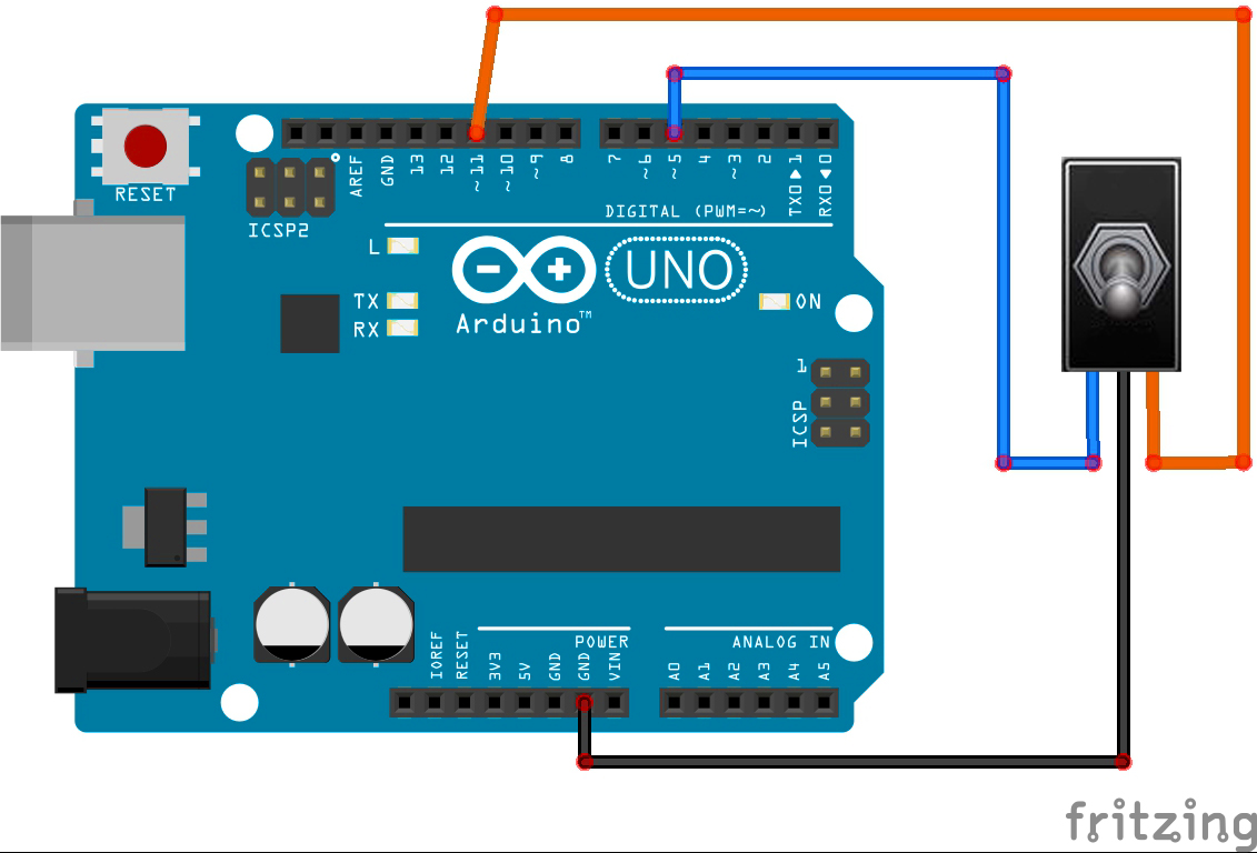
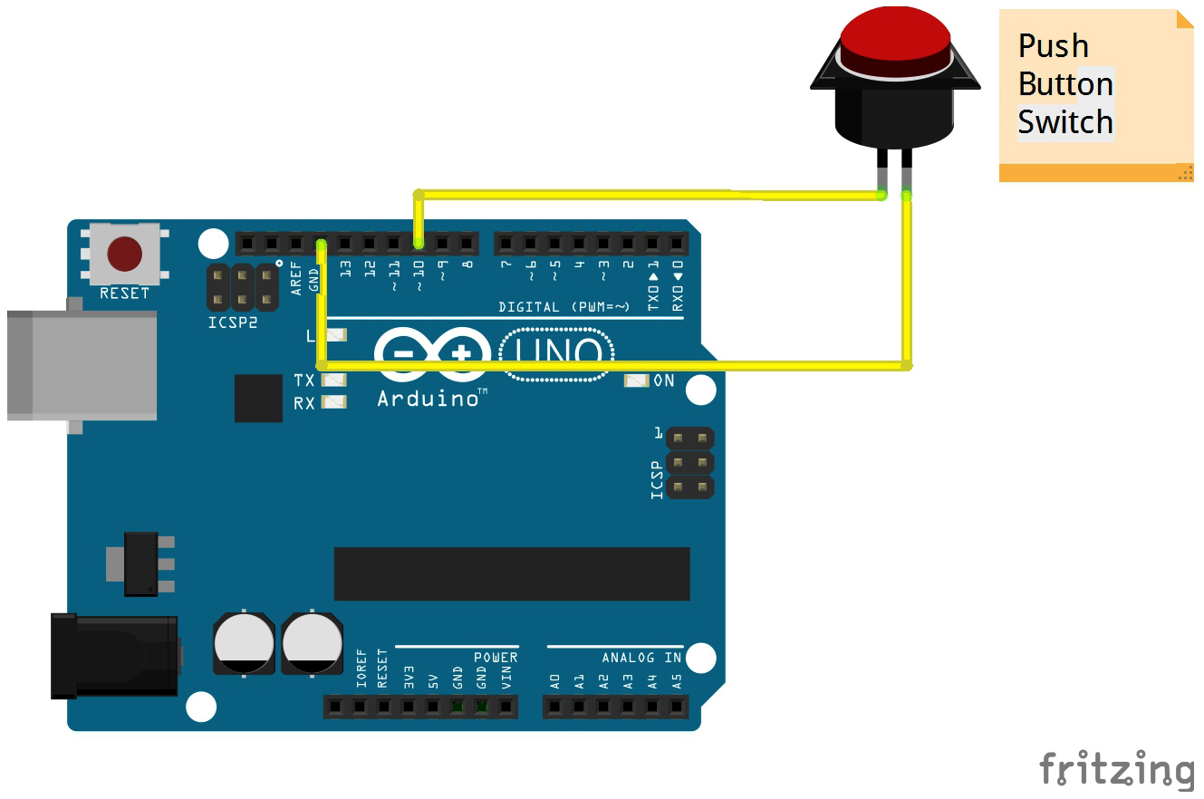
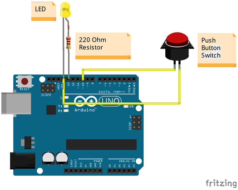
2.1 Connect your push button switch to your Arduino board at pin 10 and pin GND (ground).
| There are several pins designated as GND (ground) on the board. They are all connected together. It doesn’t matter which one you choose. |
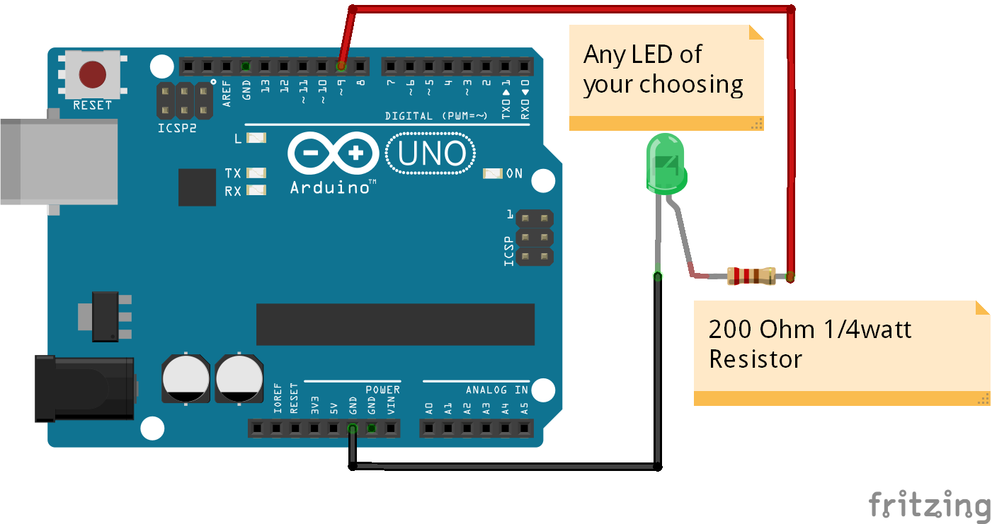
2.2 Connect your LED and current limiting resistor to the Arduino board at pin 13 and pin GND (ground). Pay attention to the polarity of the LED before you connect it. The cathode, which is the negative side always goes to pin GND. Nothing will start smoking if you connect it backwards. It just won’t work until its connected properly.
When complete your curcuit should look like this:
-
Plug your Arduino board into a USB port. If any drivers are required there will be instructions as to how to install them. It does vary between Arduino boards but it’s no different really than installing a headset or joystick. The USB port provides power to the Arduino board but you can use a wallwart providing its 12v. There is an onboard jack to plug into.
You have now completed all of the required wiring for you first switch panel.
|
Note
|
The USB port provides power to the Arduino board but many boards also have a jack that allows you use an external power supply such as a wallwart providing it supplies 7 to 12V and the centre pin is positive. |
| The Analog pin can also used as Digital Pins (on a NANO except A6 and A7). Just go further with the Numbers A0 = 14, ..... A5 = 19 |
| Most Arduino boards have a built-in LED connected to pin 13, so that pin should only be used as an output. |
Step 3: Set up the Arduino IDE
I imagine your next question is "what is an IDE". The Arduino IDE is a program that you will download and install on to your PC. You use it to write small programs (they are called "sketches") and upload them to your Arduino board. You should probably read the page describing how to use the IDE on the Arduino web site. It is very simple and you should have little to no difficulty understanding what to do. So to continue…
-
Download and install the Arduino IDE from the Arduino website.
The Arduino IDE uses what are referred to as "Libraries" to help you make various types of devices work properly using a minimum of commands. There are libraries for using LCD displays, stepper motors, servos etc. It’s a long list. We have produced such a library for using DCS-BIOS and it is called the DCS-BIOS Arduino library. As with all libraries, it was developed to make your life easier when it comes to writing a sketch. However, libraries need to be installed and this next step will guide you through that process.
-
Download the updated DCS-BIOS Arduino library Puma Fork or orginal DCS-BIOS Arduino library from GitHub.
-
Start the Arduino IDE
-
Click
Sketch → Import Library → Add Library…and then go find the ZIP file you downloaded and select it. The Arduino IDE will do the rest. That’s all there is to importing libraries into the IDE. -
Close and re-open your Arduino IDE. You are now ready to start you first sketch.
DO NOT extract it. It also doesn’t matter where you download the file to as long as YOU know where it is as you will need to point to its location in the next step.
Congratulations, you have completed all of the one-time setup steps. From now on any panel that you create will only require you to complete steps 4 and 5.
Step 4: Create a sketch for your Arduino board
You are now going to create a sketch for your Arduino board that connects it to DCS and makes your switch and LED work as in your DCS aircraft cockpit. In order to simplify this process you will begin your sketch by opening a "template" that we have provided. Until such day as you become an Arduino programming expert you will start every new sketch with this template. It provides all of the essential code necessary to communicate with DCS. It automatically reads the state of your connected switches and reports this to DCS-BIOS which then updates the switches of your DCS aircraft.
Another function of this template is to automatically gather output data from DCS. You can use this data to make gauges function, displays work or indicator lights to light up. We will provide you with several examples in the appendix.
| Take special care not to alter any of the existing code that comes with this template as you work on your sketch. |
So lets begin:
-
Click
File → Examples → DcsBios → IRQSerialto open the template program that comes with the DCS-BIOS Arduino library.
To develop a sketch for your panel, you are going to copy pieces of example code from a reference document that we have provided.
-
Go to your saved Games folder/DCS-BIOS/doc and double-click on the file
control-reference.htmlYour web browser will automatically open and display all sorts of colorful headings and code. If you see a red warning instead, you need to enable JavaScript in your web browser and reload the page.
This web page is the reference document we are referring to. It lists every single DCS module that DCS-BIOS supports, every single panel found in that aircraft, and every single corresponding switch, push button and rotary knob or whatever associated with that panel and the corresponding code that you will use to create your sketch.
Along the top of the web page, there are "filters" in the form of drop down menus that can be used to display precisely what you are looking for. You have the choice of what aircraft you would like to work with, the type of information you would like displayed (basic or advanced) and every single panel on the aircraft you chose to work with. Stay away from the advanced tab until you know what you are doing.
-
Select "A-10C" in the "Module" dropdown menu and "UFC" as "Category Filter".
The first entry should be the one for the Master Caution Light.
-
left click in the box with the yellow background to highlight the example code. Then copy the selected text to your clipboard by pressing
Ctrl+C. Now move to the Arduino IDE and paste this line in the space just below where it says "paste your code below here". -
Now go back to the control reference web page. Scroll down a bit until you come to the
UFC_MASTER_CAUTION / Master Caution Resetentry. -
As before, left click in the box with the yellow background and then copy it to your clipboard. Move to the Arduino IDE and paste this line in the space below the last one.
Did you notice the red highlighting in the control reference document? It highlights the word "PIN" or "PIN_A, PIN_B" etc. These are temporary placeholders that you will be changing.
-
Lets start with the switch that you are using to reset the Master Caution. You attached it to Pin 10 on the Arduino board. You now need to go into the Arduino IDE, to the line of code you pasted for the Master Caution Reset switch. Change the placeholder "PIN" to the pin that switch is connected to. In this particular case it was Pin 10. The word "PIN' gets replaced with 10. The line of code for the Master Caution switch should have changed as follows:
DcsBios::Switch2Pos ufcMasterCaution("UFC_MASTER_CAUTION", PIN);
DcsBios::Switch2Pos ufcMasterCaution("UFC_MASTER_CAUTION", 10);
-
You now do the same for the LED that respresents the Master Caution warning. As before, you go into the Arduino IDE, to the line of code you pasted for it. Change the word "PIN" to the pin number you connected the LED to. The word "PIN' gets replaced with 13. The line of code for the LED Master Caution warning should change as follows:
DcsBios::LED masterCaution(0x1012, 0x0800, PIN);
DcsBios::LED masterCaution(0x1012, 0x0800, 13);
When you have completed these changes, the beginning of your sketch should look like this:
#include <DcsBios.h>
#include <Servo.h>

/**** Paste your code below here ****/

DcsBios::LED masterCaution(0x1012, 0x0800, 13);
DcsBios::Switch2Pos ufcMasterCaution("UFC_MASTER_CAUTION", 10);

/**** Do not change anything below this line ****/-
Click
File → Save Asto save it under a new name.
| The Arduino IDE prevents you from saving changes to a library example. You will have to save your changes under a new name. |
Your sketch is now finished and ready for the next step.
Step 5: Copy your program to your Arduino board
Now that your sketch is done, you need to load it onto your Arduino board.
The specifics of this process may vary slightly for different Arduino boards but for the most part they all follow the same basic routine. We use the Arduino UNO in this example.
| The Arduino website has step-by-step instructions for each board. |
-
With your sketch open in the Arduino IDE you need to tell the IDE what board you are using. Do this by Clicking on
Tools → Boardand then select your board from the list that is displayed. -
Next, you will need to specify the COM port your board is connected to. Click
Tools → Portand select the port from the list.
If you are unsure of the port number, it is identified in the Control Panel/Devices and Printers page.
|
-
The final step is to initiate the upload. This is done by clicking on the Arrow in the circle just below the Edit drop down menu. When the upload begins, a green bar will apear and show the progress of the upload. When it disappears the upload is complete.
-
After loading your program onto your Arduino board, you can close the Arduino software.
Step 6: Test your new panel
DCS-BIOS comes with a script that connects a serial port to DCS. This serial port is the means by which your PC and your Arduino Board communicate. To initiate this connection you need specify the COM Port to use. You will use the same COM Port that the Arduino IDE used to program your board.
-
Double-click
connect-serial-port.cmdwhich is in the DCS-BIOS folder you previously downloaded. A console window should pop up. Type in the number of the COM port that your Arduino board is connected to and press Return. Leave the console window open.
You can now start DCS and try your new panel in action!
If you don’t want to type in the COM port number every time you run the script, you can edit the script (or a copy of it) so it always uses the same port:
-
Start Notepad++. Open the
connect-serial-port.cmdfile which is in the DCS-BIOS folder you previously downloaded. Near the top of the file, you will see a line that saysset COMPORT=ASK. ReplaceASKwith the number of the COM port you wish this script to use. For example, to use COM5, the line should look like this:
set COMPORT=5
-
Save the file and close Notepad++.
If you make a copy of the script, you need to place it in the same folder as the
original. Otherwise it will not find the socat executable.
|
Summary
You can make any panel you like using this template file.
-
Add the lines of code from the
control-reference.htmldocumentation to your sketch for the switches and/or LED’s you wish to use. -
Upload that sketch to your Arduino board.
-
Connect the appropriate switch type and/or LED to the appropriate pin number on the Arduino board.
-
Initiate the serial connection to DCS.
-
Begin using your switches and LED’s in your DCS aircraft.
What this Guide IS NOT
If your intent is to include displays and/or analog gauges with your panels you will need to have additional programming knowledge. There are displays in the aircraft that could incorporate LCD displays, LED displays or OLED displays. In addition there are analog Gauges in the cockpit that could be built using stepper motors, servos or even air core motors. With such a wide choice of components available, it really is beyond the scope of this particular document to provide instruction on every possible solution.
In Conclusion…
What we are providing is the means to allow any novice cockpit builder to create a functioning switch panel and/or LED Indicators that will interact with their DCS aircraft. Most importantly, you do not need to be a programmer or electronic engineer to accomplish this task. With DCS-BIOS, it’s straight forward.
A Closer Look at The DCS-BIOS Arduino Library
This tutorial will show you how to read the DCS-BIOS control-reference documentation to create a sketch for any panel in the cockpit.
It will cover all of the different control types that are supported by the Arduino library. The information provided at this point may require some level of knowledge with Arduino programming.
The MasterCaution Example Sketch
This section takes a closer look at the different parts of the MasterCaution example sketch.
/* use '#define DCSBIOS_DEFAULT_SERIAL' instead if your Arduino board
 *  does not feature an ATMega328 or ATMega2650 controller.
 */
#define DCSBIOS_IRQ_SERIAL (1)
#include "DcsBios.h" (2)

DcsBios::LED masterCaution(0x1012, 0x0800, 13); (3)
DcsBios::Switch2Pos ufcMasterCaution("UFC_MASTER_CAUTION", 10); (4)

void setup() {
  DcsBios::setup(); (5)
}

void loop() {
  DcsBios::loop(); (6)
}


}-
Before including
DcsBios.h, you have to define a preprocessor macro that tells the DCS-BIOS Arduino Library what mode it should operate in. If you are using an Arduino board that has either an ATMega328 or an ATMega2560 chip, such as the Uno, Pro Mini, Nano or Mega 2650 boards, useDCSBIOS_IRQ_SERIAL. If your board has a different microcontroller, you can useDCSBIOS_DEFAULT_SERIALinstead, which should work with any Arduino-compatible board but can cause problems if your sketch spends a long time updating outputs, either because you are outputting to something "slow" like displays or you are using a lot of outputs (such as trying to run a Caution Lights Panel with 48 instances ofDcsBios::LED). -
This line adds the DCS-BIOS Arduino Library to your sketch.
-
This line tells the DCS-BIOS Arduino Library that there is a switch connected to pin 10 that should be mapped to the master caution reset button.
-
This line tells the DCS-BIOS Arduino Library to use the built-in LED on your Arduino board, which is connected to pin 13, as a master caution light. Refer to the control reference documentation for more examples.
-
In your
setup()function, you have to callDcsBios::setup()to initialize the DCS-BIOS Arduino Library. -
In your
loop()function, you have to callDcsBios::loop(). This causes the DCS-BIOS Arduino library to notify DCS if any inputs (push buttons, switches, etc.) have changed, and to update any outputs (LEDs, servo motors, displays, etc.) with the latest data from DCS.
Using the Control-Reference Documentation
Recall the following part from the MasterCaution example:
DcsBios::Switch2Pos masterCautionBtn("UFC_MASTER_CAUTION", 10);
DcsBios::LED masterCaution(0x1012, 0x0800, 13);
Unless you are doing something more advanced such as using something other than a serial port to talk to your DCS computer, this is the only part you need be concerned with.
Even without knowing much about DCS-BIOS, you might have guessed that this says there is a push button connected to pin 10 that should operate the master caution button and that the LED on pin 13 should light up then the master caution button does.
But how do you know what to put here for other controls? You will have to consult the "Control-Reference" documentation.
Locating the Reference Documentation
The Control-Reference documentation is included in the doc/ subdirectory in the DCS-BIOS download. Simply double-click Control-Reference.html to open it in your web browser.
| If all you see is a big red warning, you need to enable JavaScript and reload the page. |
Learn to use the DCS-BIOS Control Reference Page (CTRL-REF Page)
With this you will be able to see the actual output of DCS-BIOS for your airframe. You can easily browse the controls, examine the behavior and from there get new takes on how to configure DCSFlightpanels.
|
Pointer Calibration Tool
The Pointer Calibration Tool can be reached via the DCS-BIOS Control Reference Page.
Some Backgrounds can found in DCS-BIOS\doc\images\PointerCal Backgrounds
Finding the Control You Are Looking For
First, select the module. Second, select the type of view. Choose Simple if it is not already displayed as the default. Finally, the "Category Filter" dropdown box will provide you with a complete listing of all the panels and you can select the panel you are looking for. ==== Supported Controls DCS-BIOS refers to switches, rotary encoders, potentiometers, push buttons etc. as "CONTROLS". The following are all of the supported Controls available in DCS-BIOS:
-
DcsBios::ActionButton -
DcsBios::Switch2Pos. defines a 2 position swich -
DcsBios::Switch3Pos. defines a 3 position switch -
DcsBios::SwitchMultiPos. defines a rotary switch, you provide how many positions -
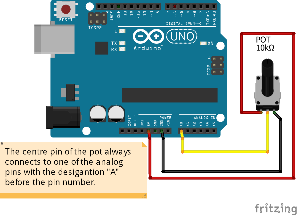
DcsBios::Pot. defines a potentiometer -
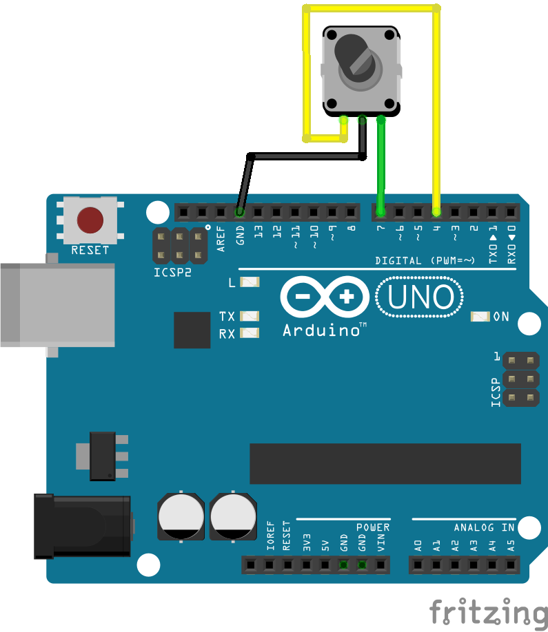
DcsBios::RotaryEncoder. defines a rotary encoder
DCS-BIOS also includes indicator LED’s in the Controls as follows:
-
DcsBios::LED. defines an LED
Each control is identified by a unique identifier and is associated with a category, which is usually the panel it is found on in the DCS aircraft cockpit.
DcsBios::SwitchPos2 ahcpCicu("AHCP_CICU", PIN);
-
whereas
ahcpCicuindicates the CICU switch on the AHCP panel. -
The first notation between the brackets
"AHCP_CICU"is a placeholder for a piece of data that gets sent to DCS when a change occurs to a pin on the Arduino board. -
The second notation
PINis also a placeholder however, you have to replace it with the pin number that your control is attached to. In the Control-Reference document, placeholder that require you to assign a specific pin number to are always highlighted in"RED" There also a few knobs/switches in your cockpit represented with two separate controls. For example, the volume controls on the A-10C intercom panel have one DCS-BIOS control for the volume and a separate control for the mute function.
Input Interfaces
-
To make sense of the following, select "Advanced" in the "View" dropdown box at the top of the page.
An input interface describes the means by which controls in the cockpit can be manipulated. .Types of input interfaces
- set_state
-
If a control supports the set_state interface, its current state can be set by sending it a number as an argument. For example, you can set the TACAN mode dial in the A-10C to the
A A RECposition by sendingTACAN_MODE 3.The range of acceptable values is 0 to the maximum value of the control’s first output. The reference documentation will offer example code for a
DcsBios::SwitchMultiPosand (where appropriate) aDcsBios::Switch2PosorDcsBios::Switch3Pos. - fixed_step
-
If a control supports the fixed_step interface, you can increase its position with an
INCargument and decrease its position with aDECargument. An example would be a rotary encoder used to change the frequency of a VHF radio.The reference documentation will offer example code for a
DcsBios::RotaryEncoder. - action
-
This represents an action such as toggling a toggle switch or changing the X/Y digit of the TACAN channel.
The reference documentation will offer example code for a
DcsBios::ActionButton. - variable_step
-
If a control supports the variable_step interface, you can increase or decrease its position by a certain amount by sending
+NUMBERor-NUMBERas an argument, whereNUMBERis an integer.The reference documentation will offer example code for a
DcsBios::RotaryEncoder. The default step size is 3200. You will need to experiment to get the right sensitivity.
Outputs
Each DCS-BIOS control can have multiple related outputs. An output represents a piece of information that is exported from DCS, for example the position of the flaps position indicator.
Outputs come in two types:
- Integer outputs
-
Most outputs are integers. Each integer output has an associated maximum value and a minimum value of 0.
The reference documentation will offer code examples for
DcsBios::LEDandDcsBios::ServoOutputwhere appropriate.The first code snippet for integer outputs is meant to be inserted into the
onDcsBiosWritefunction if the DCS-BIOS Arduino library cannot do what you want. It shows you how to extract the value using the address, mask and shift value of the output.To learn about the meaning of the address, mask and shift value of an output, please refer to the developer guide. - String outputs
-
Some values (such as radio frequencies) are exported as character strings. The reference documentation will provide a code example that uses a
DcsBios::StringBufferto execute a piece of code whenever the value changes.Because there are many different types of displays (7-segment, character, graphical) and different ways to connect them to a microcontroller (direct, I2C, SPI), the DcsBios library does not include code to handle them. For most common combinations of display type and connection method, you can find other Arduino libraries online that allow you to talk to them.
Copy and Paste Example Code
To use the example code from the reference documentation in your Arduino sketch, you first have to choose which code example to copy. That depends on what type of control you want to connect.
For example, you might want to use a rotary switch for the TACAN mode
dial in the A-10C and use the DcsBios::SwitchMultiPos code snippet. For the same control, you could also choose to use
a rotary encoder.
If the "Simple" view mode, the reference documentation displays only the "most appropriate" code example for each control.
After choosing a code example, copy it to your Arduino sketch (refer back to the MasterCaution example to see where to copy it) and replace all the parts in red with your own values (usually the pin numbers that this control is connected to).
Refer to the next section for more detailed information on the individual classes, including example circuits.